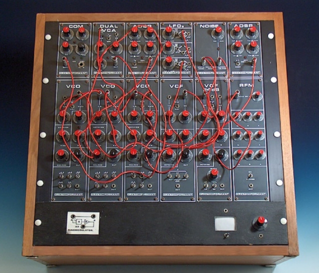
 In the old Formant synt where this synth is based upon a number of connections are fixed (internaly wired). The VCO outputs are connected to the VCF and the VCF is connected to the VCA. Both VCF and VCA have there own fixed ADSR envelope module etc.. All the other connections are made with so called patch cords. Put a patch cord in the TRI output bus of the LFO module and put the other end of the patch cord in the FM bus of an VCO module and you can frequency modulate the VCO with the LFO etc..
In the HV-Formant there is no internal wireing and no patch cords. Al the outputs of the modules are connected to one or more signal terminals. From these terminals you can select which signal you want to use as input for a module.
There are 5 input terminal types:
- Control (CV) terminals The CV terminals are located on the VCO and the VCF modules and are used to control the basic pitch or frequency of the module.
- Modulation (AM,FM,PM,TM etc) terminals These are found on almost al the modules and are used for modulation.
- Gate (GATE) terminals The gate terminals are used to start the envelope curve on the ENV1,ENV2 and ENV3 modules.
- Internal Signal terminals On most of the old analog synth's basic routing is fixed (internaly wired). On the HV-Formant even these signals are selectable. You find the internal input signal terminals on the bottom of the VCF1, VCF2, RFM and VCA modules.
- External Signal (ES) terminals Next to the internal signal input terminals the VCF1, VCF2, RFM and VCA modules also have an extra input signal terminal (ES). On this terminal you can find the non regulate signals of the VCO's, VCF's, RF's and internaly generate White Noise and coloured noise.
Voice selection
At the VOICES section you determine the voice allocation. Most of the patches use Poly 4 this means that you can press a maximum of 4 key's that wil each get a single voice. the fifth key that you press steels a voice of an other key. If you select mono only 1 key at a time will sound which is interesting for lead patches.
Unison means that you can allocate more than one voice to a single pressed key. With the Unison knob you can detune the Unison voices. The total number of voice used is a multiplication of the Mono to 16 voice selection times the Unison selection.
Warning!! You should watch out if you select more than 8 voices because this can overload the processor.