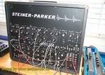
 The HV-Formant synth has a total of 66 input terminals. With these terminals you make connections between the modules. On the old analog synths these connections where made with patch cabels between the outputs and inputs of the modules. (see picture)
The HV-Formant has no output terminals. All the outputs of the modules are routed to different input terminals. So if you for instance want to modulate the frequency of VCO1 whith a low frequency sinus wave from the LFO module, you select SIN1 at the VCO1 FM input terminal.
The HV-Formant synth has a total of 66 input terminals. With these terminals you make connections between the modules. On the old analog synths these connections where made with patch cabels between the outputs and inputs of the modules. (see picture)
The HV-Formant has no output terminals. All the outputs of the modules are routed to different input terminals. So if you for instance want to modulate the frequency of VCO1 whith a low frequency sinus wave from the LFO module, you select SIN1 at the VCO1 FM input terminal.
There are 5 input terminal types:
|
Control (CV) terminals The CV terminals are located on the VCO and the VCF modules and are used to control the basic pitch or frequency of the module. | |
| KEY | Midi input comming from your keyboard or VST host |
| FIX | A fixed frequency of 440Hz |
| CV1 | Frequency comming from the SEQUENCER module |
| CV2 | Frequency comming from the SEQUENCER module |
|
Gate (GATE) terminals The gate terminals are use to start the envelope curve on the ENV1,ENV2 and ENV3 modules. | |
| KEY | Gate comming from Keyboard or host |
| OFF | Switches the module off so that it doen't consume processor power |
| CV1 | Gate comming from the SEQUENCER module |
| CV2 | Gate comming from the SEQUENCER module |
| GATE1 | Gate comming from the SEQUENCER module |
| GATE2 | Gate comming from the SEQUENCER module |
| S/H | Gate comming from the S/H module |
|
Internal Signal terminals On most of the old analog synth's basic routing is fixed (internaly wired). On the HV-Formant even these signals are selectable. You find the internal input signal terminals on the bottom of the VCF1, VCF2, RFM and VCA modules. | |
| None | The input is left open |
| VCO1 | Regulated output of the VCO1 module |
| VCO2 | Regulated output of the VCO2 module |
| VCO3 | Regulated output of the VCO3 module |
| VCOA | Sum of Regulated outputs of the VCO1,VCO2 and VCO3 modules |
| VCF1 | Regulated output of the VCF1 module |
| VCF2 | Regulated output of the VCF2 module |
| RFM1 | Regulated output of filter RFM1 of the RFM module |
| RFM2 | Regulated output of filter RFM2 of the RFM module |
| RFM3 | Regulated output of filter RFM3 of the RFM module |
| RFMA | Sum of all the Regulated outputs of the RFM module |
| MIX1 | Output of the MIX1 module |
| MIX2 | Output of the MIX2 module |
| MIX3 | Output of the MIX3 module |
| WHIN | Fixed level of internal generated white noise |
| COLN | Fixed level of internal generated coloured noise |
|
External Signal (ES) terminals Next to the internal signal input terminals the VCF1, VCF2, RFM and VCA modules also have an extra input signal terminal (ES). On this terminal you can find the non regulate signals of the VCO's, VCF's, RF's and internaly generate White Noise and coloured noise. | |
| None | The input is left open |
| WHIN | Fixed level of internal generated white noise |
| COLN | Fixed level of internal generated coloured noise |
| VCO1 | None regulated output of the VCO1 module |
| VCO2 | None regulated output of the VCO2 module |
| VCO3 | None regulated output of the VCO3 module |
| VCF1 | None regulated output of the VCF1 module |
| VCF2 | None regulated output of the VCF1 module |
| RFM1 | None regulated output of filter RFM1 of the RFM module |
| RFM2 | None regulated output of filter RFM2 of the RFM module |
| RFM3 | None regulated output of filter RFM3 of the RFM module |
| MIX1 | Output of the MIX1 module |
| MIX2 | Output of the MIX2 module |
| MIX3 | Output of the MIX2 module |
|
Modulation (AM,FM,PM,TM etc) terminals These are found on almost al the modules and are used for modulation. | |
| DC0 | Fixed value 0 (disable regulation) |
| DC1 | Fixed value 1 (enable regulation between 0 - 1) |
| SIN1 | Sinus wave output of LFO1 |
| SIN2 | Sinus wave output of LFO2 |
| TRI1 | Triangle wave output of LFO1 |
| TRI2 | Triangle wave output of LFO2 |
| SQU1 | Square wave output of LFO1 |
| SQU2 | Square wave output of LFO2 |
| RUP1 | Ramp up (0 - 1) output of LFO1 |
| RUP2 | Ramp up (0 - 1) output of LFO2 |
| RDWN1 | Ramp down (1 - 0) output of LFO1 |
| RDWN2 | Ramp down (1 - 0) output of LFO2 |
| ENV1+ | Envelope curve (0 - 1) of the ENV1 module |
| ENV1- | Envelope curve (1 - 0) of the ENV1 module |
| ENV2+ | Envelope curve (0 - 1) of the ENV2 module |
| ENV2- | Envelope curve (1 - 0) of the ENV2 module |
| ENV3+ | Envelope curve (0 - 1) of the ENV3 module |
| ENV3- | Envelope curve (1 - 0) of the ENV3 module |
| GATE1 | Time variable (1 or 0) signal coming from the SEQUENCER module |
| GATE2 | Time variable (1 or 0) signal coming from the SEQUENCER module |
| MOD1 | Level variable (-1 - 1) signal coming from the SEQUENCER module |
| MOD2 | Level variable (-1 - 1) signal coming from the SEQUENCER module |
| S/H | Output of S/H Module |
| VEL | Midi velocity (0 - 1) from CONTROLLERS module |
| AFT | Midi aftertouch (0 - 1) from CONTROLLERS module |
| MODW | Midi modulation (0 - 1) |
| PITW | Midi pitchbend (-1 - 1) |
| PITCH | Midi note (-1 - 1) |
| BEND | Value of BEND knob (-1 - 1) from CONTROLLERS module |
| INT1 | Value of INT1 knob (0 - 1) from CONTROLLERS module |
| INT2 | Value of INT2 knob (0 - 1) from CONTROLLERS module |
| INT3 | Value of INT3 knob (0 - 1) from CONTROLLERS module |
| MIX1 | Output of the MIX1 module |
| MIX2 | Output of the MIX2 module |
| MIX3 | Output of the MIX2 module |
| WHIN | Fixed level of internal generated white noise |
| COLN | Fixed level of internal generated coloured noise |
| VCO1 | None regulated output of the VCO1 module |
| VCO2 | None regulated output of the VCO2 module |
| VCO3 | None regulated output of the VCO3 module |
| VCF1 | None regulated output of the VCF1 module |
| VCF2 | None regulated output of the VCF1 module |
| RFM1 | None regulated output of filter RFM1 of the RFM module |
| RFM2 | None regulated output of filter RFM2 of the RFM module |
| RFM3 | None regulated output of filter RFM3 of the RFM module |