 This module is where the HV-Formant is named upon. In the original Formant the Resonant Filter Module had 3 small bandpass filters of which you could set the Cutoff frequncy (f0) the Resonance or quality (Q) and the output. The module was placed at the end of the sound chain and gave the possibility to favour 3 selected frequency bands in the frequency domain (formant creating).
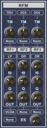
Within the HV-Formant this module is much more advanced. Due to 100% modulair setup it is now possible to use the RF1,RF2 and RF3 filters any where you like in the sound chain. Next to the bandpass filter in the original version you can now choose other filter types. It is also possible to Timbre Modulate each filter strip.
Inputs
Each filter strip has its own internal input terminal from where you can select a sound signal, see Input Terminals. At the ES section you can select an extra signal that is sent to all three strips. The strength of the ES signal is determined by the ES knob.
The filters
As of version 1.03 you can make a selection out of 4 filter types. The standard ones are 12dB Low Pass (LP), Band Pass (BP) and High Pass (HP), see "Introduction to Subtractive Synthesis" for an explanation of the standard filter types. The f0 knob determines the cutoff or centre frequency, the Q knob determines the Quality or resonance of the filter and the OUT knob determines how much of the filtered signal is sent to the output. The f0 frequency of these three standard filter types can be modulated through the Timbre Modulation (TM) section of the filter strip.
PEQ The Parametric EQualizer filter
This is a special filter implemented since v1.03. It is in principle a band pass or band reject filter with a variable center frequency, a variable bandwidth and a variable gain. If you select this filter, the TM knob wil change in a PEQG, Gain knob. With this knob you determine how much the frequencies within the selected frequency band are amplified (passed or rejected). The center frequency is set with the f0 knob. The Q knob is used to set the bandwidth of the filter, it sets the frequency range around the center frequency. The OUT knob determines how much of the filtered signal is sent to the output.
TM Section
With Timbre Modulation you change the f0 center frequency according the selected modulation signal. The debt of the modulation is determined by the TM knob. You can choose to invert the modulation signal. The Timbre Modulation is only available with LP,BP or HP filter types. If you select the PEQ filter, the modulation sinal is ignored and the knob is used to set the gain of the filter.
Output
The generated signals RFM1, RFM2 and RFM3 of this module are sent to all the internal and external signal terminals.