 This module is where the sound comes from. VCO means Voltage Controlled Oscilator. The name VCO comes form the Analog era where the hight of a tone (the frequency of the oscilator) was controlled by a controll voltage (CV) comming from the keyboard or other devices (1 volt per octave).
Constructing an Wave
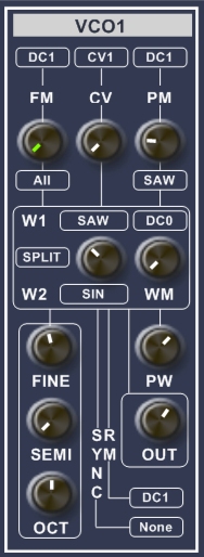
At the W1 and W2 terminals you can make a choice out of 4 basic wave
forms (SIN,TRI,SAW,SQU) or an wave coming from an other VCO. The two waves can be mixed (MIX), split (SPLIT) or morpht (MORPH) by the Knob in between W1 and W2 to generate a new Wave.
The maximum left position of the knob results in 100% W1. This mixing, splitting or morphing can also be modulate by an external signal. I call this wave modulation (WM).
MIX
With wave mixing you get a summation of x% of W1 and y% of W2 determined by the Knob as output of the VCO.
SPLIT
With wave splitting the 360 degrees wave cycle of W1 and W2 ar split in x% of W1 and Y% of W2. The result is a new wave cycle with lots of harmonics. You can also select "None" at W1 or W2 to cut off a part of the wave.
MORPH as of v1.04
With wave morphing you mix W1 and W2 over one 360 degree cycle. With the knob at the left position no morphing is performed and only W1 is sent to the output. With the knob at the right position W1 is graduatly mixed to W2 over the first 180 degrees of the cycle and back to W1 over the last 180 degrees. The knob determines the percentage of W2 to mix to. Swapping W1 and W2 can generate a completely different effect. Wave morphing enables you to generate subtal changes in the original waves and produces a lot less harmonics than wave splitting.
Frequency of the VCO
The basic frequency of the VCO is set at the CV section and tuned by the FINE, SEMI and OCT knobs. You can modulate the basic frequency at the FM section.
CV section
This is the main frequency controll of the VCO. CV means Controll Voltage, this is a term from the analog era. At the input terminal you can select: KEY, the controll signal (pitch, frequency) is comming from your midi keyboard or sequencer. FIX, the frequency is fixed at 440Hz, you can change this frequency with the knob. CV1 or CV2, The frequency is comming from the SEQUENCER. With the knob you determine how much the frequency should follow the controll frequency. Normaly you set this at the max value (100%). If you put it at 0 (0%) the VCO wil do nothing.
FM section
At the FM section you can frequency modulate the VCO. At the top terminal you select the modulation signal and with the knob you determine the depth of the modulation. At the lower terminal you can select the wave that receives the modulation. This enables you to modulate only one wave in the W1 and W2 selection. If you choose RAMP at this selection the internal synching mechanism of the VCO is modulate which can result in strange effects.
PM section
At this section you determine the ammount of Pulse (on the SQUARE wave) or Phase (at the other wave forms) modulation. The target wave is selected at the bottom terminal. The modulation signal is selected at the top terminal. The Knob determines the depth of the modulation.
Pulse Modulation
The basic pulse width of the SQUARE wave is regulate with the PW knob (see PW Section). The PM amount determines how much this pulse width is modulated.
Phase Modulation
Phase modulation is possible on the other waves (SIN,SAW,TRI). It determines where the wave starts. 0 - 360 degrees. Most usefull is to select DC1 at the input terminal select (SAW) as target wave. You can now select with the knob which part of the Saw tooth wave you want to use in the W1,W2 SPLIT wave configuration.
RM Terminal
Ring Modulation is found on many old analog synths. It generates these special Bell like sounds. The first electronics that realised Ring Modulation actualy looked like a Ring, so now you know where the the name comes from. In the Digital domain RM is actualy quite simple. It is a simple multiplication of the VCO output with a modulation signal. If you take a high frequency modulation signal (comming from an other VCO) you can generate Bell like sounds. If you take low frequency (LFO signal or ENVelope curves) you can Amplitude Modulate the VCO output. I use the RM terminal offen with a signal comming from the envelope(ENV) modules to pre amplifie the signal before sending it to an VCF. Warning! If you don't want to use RM leave this terminal on DC1.
SYNC Terminal
Synchronizing Waves is proberbly the most difficult feature on this Synth.
An wave is repeating it self after it's 360 degree cycle is complete, the time the cycle takes is called frequency and is expressed in Hertz (Hz). A tone or wave of 100Hz, repeats it self 100 time per second. Within each VCO a SYNC pulse is generate corresponding the basic frequency determined by CV + FM. This pulse can be used to Sync other waves e.g. to restart (begin at 0 degrees) an other wave, when this wave crosses 0 degrees.
External SYNC
With external Sync you synchronise the VCO to an other VCO. In this situation the SYNC pulse from the other VCO restarts the W1 and W2 waves of this VCO.
Internal SYNC
With internal synchronisation you can sync the wave selected at the FM terminal to the internaly generated SYNC pulse. If you for instance want to generate the populair Sync-Saw wave from VCO1:
- Select SAW as the FM wave and select DC1 as the Modulation signal put the FM knob at +/- 20%.
- Select SAW at W1, select SPLIT or MIX and turn the Knob to the left to get 100% W1, SAW.
- Select FM at the SYNC terminal.
- Turn the FM knob to hear how the frequency of the VCO stay's the same but the charcter of the sound changes.
VCO Output
The VCO produces two outputs. One is the regulated output, the amplitude of this signal is determined by the OUT knob. This signal is sent to the Internal Terminals (found at the input section of VCF1, VCF2, RFM and VCA modules. The other output is none regulated e.g. maximum amplitude and is connected to the Modulation terminals and External (ES) terminals. See also: Input Terminals
Warning For normal use of the VCO the RM terminal should be on DC1!!
See also: