|
|
With Timbre modulation you can dynamically change the cutoff frequency of the filter. At the input terminal you can select the modulation signal. With the knob you can regulate the depth of the modulation. With the bottom terminal you can invert (multiply by -1) the input signal.
|
|
|
CV means Controll Voltage and is a term from analog synth era. It is the controll parameter for the tracking of the filter. If you select KEY at the input terminal, the tracking is controlled by the note played on your key board or sequencer program (Midi input). Other options are CV1 and CV2 comming from the SEQUENCER module or FIX, a constant value (440hz). With the CV knob you determine the amount of tracking (half way = 100%)
|
|
|
At this section you set the Envelope that controls the filter. It is however the same as the TM section so you can select any modulation signal. |
|
| At this section you can select the filter type. Many different filters can be selected and the list may grow with new versions of the synth. See the filter list. If you don't use this filter, select Off to preserve processor power. |
|
| At this section you can tune the Cutoff frequency of the filter. The red marker on the CUT knob means that in this example the knob is connected to a Midi controller. See the midi section of the synth. |
Q
OUT
IN
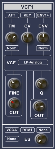 VCF1 and VCF2 are the main filters of the synth. With filters you are able to manipulate frequencys in a sound. For instance a lowpass filter only alows frequencies below a surtain frequency (CUT) in the source signal to pass through. The cutoff (CUT) value can be timbre modulate (TM) or controlled by a envelope (ENV). VCF1 and VCF2 are Tracking Filters, this means that the cutoff point is able to follow the ground frequency of the input signal. Like the VCO the name VCF is comming from the analog era and stands for Voltage Controlled Filter. The tracking is done by a controll voltage (CV). If you have selected KEY (keyboard) at VCO1 and selected VCO1 as the input for the filter than if you also select KEY at the CV terminal of the VCF and put the CV knob at half, the filter will follow the ground frequency of the VCO.
Filter list
- Lowpass
- Highpass
- Bandpass
- Notch
- Badboy
- LP-Analog
- RBJ-Lowpass
- RBJ-Bandpass1
- RBJ-Bandpass2
- RBJ-Highpass
- RBJ-Notch
- RBJ-Allpass
|
| Copyright Notice.
This article, including but not limited to all text and diagrams, is the intellectual property
of E.W. Fonken, and is Copyright © 2008. Reproduction or re-publication by any means whatsoever,
whether electronic, mechanical or electro- mechanical, is strictly prohibited under International Copyright laws.
The author grant the reader the right to use this information for personal use only,
and further allows that one (1) copy may be made for reference. Commercial use is prohibited
without express written authorisation from E.W. Fonken. |
Page published and copyright © 21-5-2008
|