 The LFO module consists of two independant Low Frequency Oscilators, LFO1 and LFO2. Each oscilator generates 5 wave forms. that you can use to modulate other modules.
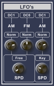
The frequency range of the LFO's is +/- 0.02 Hz to 20Hz. The speed adjustment has two modes. SPD, the frequency is changed exponentially from 0.02 Hz to 20 Hz or beat synched by the Host's tempo (default 120BPM) S 4/1 to S 1/64. The LFO's also have two running modes:
Amplitude Modulation
The output amplitude of each LFO is controlled by the AM section. You can select a modulation signal from the AM input terminal. The knob determines the modulation depth. In most cases you select DC1 and set the knob to determine the output level of the LFO. Other usefull modulation signal are VEL (Midi note velocity), with this selection the amplitude of the LFO wave is determined by the note velocity. AFT, now the amplitude is determined by Midi channel Aftertouch. The ENV3 module is specialy designed to modulate the LFO with the delay on ENV3 you can pros pone the output of the LFO.
Important! If you select DC0 at the AM input terminal, The LFO is switched off to preserve processor power. The modulation signal can be inverted (1-modulation signal) by selecting Inv at the AM mode terminal.
Frequency Modulation
LFO2 has also an option for frequency modulation. As an example, if you select the Ramp up wave (RUP1) of LFO1 at the FM input terminal the frequency of LFO2 will gradualy change over time.
Output routing
All the outputs of LFO1 and LFO2 are routed to the modulation bus.
| SIN1 | Sinus wave output of LFO1 |
| SIN2 | Sinus wave output of LFO2 |
| TRI1 | Triangle wave output of LFO1 |
| TRI2 | Triangle wave output of LFO2 |
| SQU1 | Square wave output of LFO1 |
| SQU2 | Square wave output of LFO2 |
| RUP1 | Ramp up (0 - 1) output of LFO1 |
| RUP2 | Ramp up (0 - 1) output of LFO2 |
| RDWN1 | Ramp down (1 - 0) output of LFO1 |
| RDWN2 | Ramp down (1 - 0) output of LFO2 |